Welcome to top Matlab Articles Provider in World. We are a team of Matlab Experts available online 24x7. Get help in your Matlab Projects. matlabsolutions.com
Looking for inspiring MATLAB projects to sharpen your skills or impress in your next assignment? At MATLABSolutions.com , we’ve curated the top 12 MATLAB projects that showcase the power of MATLAB in signal processing, image analysis, machine learning, and more. These hands-on examples, complete with code and explanations, are perfect for beginners and advanced users alike. Dive in and explore the best MATLAB projects to elevate your expertise! Signal Smoothing with Moving Average Filter Master signal processing by smoothing noisy data using MATLAB’s movmean function. This project cleans a synthetic sine wave, teaching you noise reduction basics. Ideal for audio or sensor data analysis. Get the code at MATLABSolutions Projects Image Edge Detection Using Canny Filter Explore image processing with MATLAB’s Canny edge detection algorithm. This project highlights edges in any photo, perfect for computer vision applications. Download the script and try it on your own images! Bitcoin Price ...
How does the signal actually change from DC to AC within an astable multivibrator inverter?
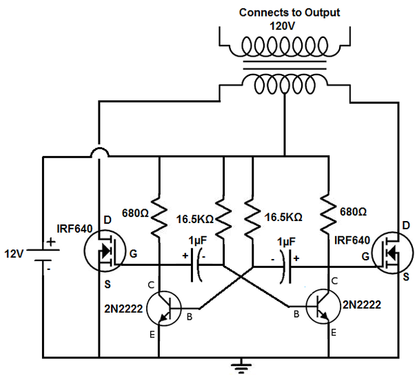
I’m going to paste the circuit from the linked article here, so it’s easier to discuss:
The ‘astable multivibrator’ part is everything in the circuit other than the two IRF640s and the transformer.
The name ‘multivibrator’ is a rather quaint description of a simple RC relaxation oscillator. It’s called that because it produces square waves, which contain a great deal of harmonics or overtones of the base switching frequency; that is multiple vibrations. The linked article erroneously claims this circuit produces “a closely resembling sinusoidal waveform” [sic], which is simply untrue.
To understand its operation, it’s best to look at the circuit after it has been running for a while, because the situation at the moment that power is applied is a bit hit-and-miss. So let’s assume the the left-hand 2N2222 (I’ll call this TR1) is switched ON, and the right hand 2N2222 (TR2) is OFF. For this to be true, the base of TR1 must be above 0.6v, and it gets its base current through the 16.5K resistor. When TR1 is ON, its collector terminal is close to 0v. On the other side, TR2 is OFF, so its collector terminal is at +12v. The left-hand capacitor will now start to charge up through the 16.5K resistor until the voltage reaches 0.6v. This switches TR2 ON, bringing its collector to 0v. This brings the other side of the right-hand capacitor sharply negative, which instantly shuts off TR1. Now the right-hand capacitor starts to charge up from the negative voltage to +0.6v, and once it reaches that value, TR1 turns ON again, bringing its collector to 0v, which causes a sharp negative spike on the base of TR2 through the left-hand capacitor. This shuts off TR2, and the cycle repeats, endlessly. (Note that the diagram shows the capacitors as electrolytic types, but since they are operating in both directions here, you should never use electrolytics in such a circuit.)
So anyway, we now have the two 2N2222 transistors switching ON, and when one does, it switches the other OFF, and then after a short delay while the capacitor recharges, the opposite happens, in an endless cycle. Tick-tock, tick-tock. The two IRF640s are power MOSFETS which switch ON when the gate terminal is at a high voltage compared to the source (S) terminal. So these also switch in antiphase. They are connected to the primary of the transformer, and the centre-tap is fed with +12v. Therefore, when one MOSFET is on, current flows through half of the transformer primary winding in one direction, then when the other switches on, it flows the opposite way through the other half of the transformer primary. The voltage is stepped up by the transformer which also eliminates some of the higher harmonics in the switching, so what you get at the output is a very crude AC supply with a lot of remaining harmonics. As an inverter, this is pretty poor, and will probably not work very well powering anything sensitive. A good AC signal is a pure sine wave, but this circuit is not going to produce that.
The frequency of the switching is set by the 16.5k resistors and the 1µF capacitors, and is ~0.693 x 2RC, (the linked article quotes an incorrect ‘formula’ for the frequency) which in this case is about 44 Hz — near to, but not very precisely, the mains frequency — and in any case, component tolerances will affect this, especially capacitors, which are not usually precision components. I wouldn’t recommend this as a way to build a real inverter — the output is too dirty and the frequency isn’t well controlled. I would also caution that the output from this could still be just as lethal as ‘real’ mains voltage, so if you plan to build it, be careful.
Looking for inspiring MATLAB projects to sharpen your skills or impress in your next assignment? At MATLABSolutions.com , we’ve curated the top 12 MATLAB projects that showcase the power of MATLAB in signal processing, image analysis, machine learning, and more. These hands-on examples, complete with code and explanations, are perfect for beginners and advanced users alike. Dive in and explore the best MATLAB projects to elevate your expertise! Signal Smoothing with Moving Average Filter Master signal processing by smoothing noisy data using MATLAB’s movmean function. This project cleans a synthetic sine wave, teaching you noise reduction basics. Ideal for audio or sensor data analysis. Get the code at MATLABSolutions Projects Image Edge Detection Using Canny Filter Explore image processing with MATLAB’s Canny edge detection algorithm. This project highlights edges in any photo, perfect for computer vision applications. Download the script and try it on your own images! Bitcoin Price ...
I have a 1x12 cell in Matlab and each element of this cell has a 3d matrix. I want to make the mean of these 3d matrices, so that I obtain a 3d matrix that has the same dimensions of each one of the 3d matrices of the cell and that is the mean of the 12 3d matrices. How can I do this operation ? I tried to extract each cell and create a 4d matrix so that I could do mean(fourdmatrix,4) . However, it seems not possible to create a 4d matrix. Ideed, a code like this: cell={threedmatrixA, threedmatrixB, ...} fourdmatrix=[]; for i=1:12 fourdmatrix(i)=cell{i}; end does not work. How can I do it ? NOTE:- Matlabsolutions.com provide latest MatLab Homework Help, MatLab Assignment Help , Finance Assignment Help for students, engineers and researchers in Multiple Branches like ECE, EEE, CSE, Mechanical, Civil with 100% output.Matlab Code for B.E, B.Tech,M.E,M.Tech, Ph.D. Scholars with 100% privacy guaranteed. Get MATLAB projec...
PID tuning to meet conditions for settling time and overshoot while a stable system with minimum peak time and zero velocity error. So I am trying to find the gain values for a PI control system that would give me a settling time not exceeding 6 seconds, and an maximum overshoot not going over 5% while ensuring that the peaktime is the lowest it can be, and that the system is stable, and also has zero velocity error. I have written the following code. Starting with a kp and ki value of 1 each, I get a system that gives desirable overshoot and settling time, but I am wondering if the peaktime can be even lower while still having settling time <= 6 and overshoot <= 5. I am using the following toolboxes: Control System Toolbox Questions Using the rlocus function, I have also shown that the real parts of the poles are negative, so this demonstrates that my system is stable right? Also am I using Lsim correctly to determine if velocity error is zero? The resultant graph has a gr...
Comments
Post a Comment